-

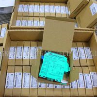
Intrinsic Safety Barriers Isolated Barrier KFD2-SH-EX1
Pepperl+Fuchs,Intrinsic Safety Barriers,Isolated Barrier,KFD2-SH-EX1
KFD2-SH-EX1
- Detailed introduction
- Ask an Expert >
Function
This isolated barrier is used for intrinsic safety applications.
The device transfers digital signals (SN/S1N proximity sensors or approved dry contacts) from a hazardous area to a safe area.
The input controls one relay contact output with 3 NO contacts (one output is in series to the both output relays for the safety function), one relay contact output with one NO contact, and one passive transistor output.
Unlike an SN/S1N series proximity sensor, a mechanical contact, requires a 10 kΩ resistor to be placed across the contact in addition to a
1.5 kΩ resistor in series.
Lead breakage (LB) and short circuit (SC) conditions of the control circuit are continuously monitored. During an fault condition, the fault indication output energizes and outputs I and II de-energize.
For safety applications up to SIL3, output I must be used. For safety applications up to SIL2, output I and output II can be used.
Technical data
| General specifications | ||
|---|---|---|
| Signal type | Digital Input | |
| Functional safety related parameters | ||
| Safety Integrity Level (SIL) | SIL 3 | |
| Systematic capability (SC) | SC 3 | |
| Performance level (PL) | PL d | |
| Supply | ||
| Connection | Power Rail or terminals 22+, 23+, 24- | |
| Rated voltage | 20 ... 35 V DC | |
| Ripple | ≤ 10 % | |
| Rated current | ≤ 130 mA | |
| Power dissipation | 2.1 W | |
| Power consumption | max. 2.3 W | |
| Input | ||
| Connection side | field side | |
| Connection | terminals 10+, 12- | |
| Open circuit voltage/short-circuit current | approx. 8.4 V DC / approx. 11.7 mA | |
| Lead resistance | ≤ 50 Ω, in hazardous area cable capacitances and inductivities are to be taken into account | |
| Switching point | ||
| Relay de-energized | I < 2.1 mA and I > 5.9 mA | |
| Relay energized | 2.8 mA < I < 5.3 mA | |
| Response delay | ≤ 1 ms | |
| Output | ||
| Connection side | control side | |
| Connection | output I: terminals 13, 14 ; output II: terminals 15, 21 ; output III: terminals 16+, 17- | |
| Output I | relay , signal | |
| Contact loading | 50 V AC/1 A/cos φ > 0.7; 24 V DC/1 A resistive load | |
| Mechanical life | 50 x 106 switching cycles | |
| Output II | relay , signal | |
| Contact loading | 50 V AC/1 A/cos φ > 0.7; 24 V DC/1 A resistive load | |
| Mechanical life | 50 x 106 switching cycles | |
| Output III | electronic output, passive , fault signal | |
| Rated voltage | 10 ... 30 V DC | |
| Signal level | 1-signal: (L+) -2.5 V (7 mA, short-circuit proof) / 0-signal: blocked output (Leakage current ≤ 10 µA) | |
| Transfer characteristics | ||
| Switching frequency | 5 Hz | |
Your product, or application questions answered in one business day by our team of experts.
! Please fill in all fields before submitting your question. Pepperl+Fuchs values your privacy. Please read our privacy policy.

